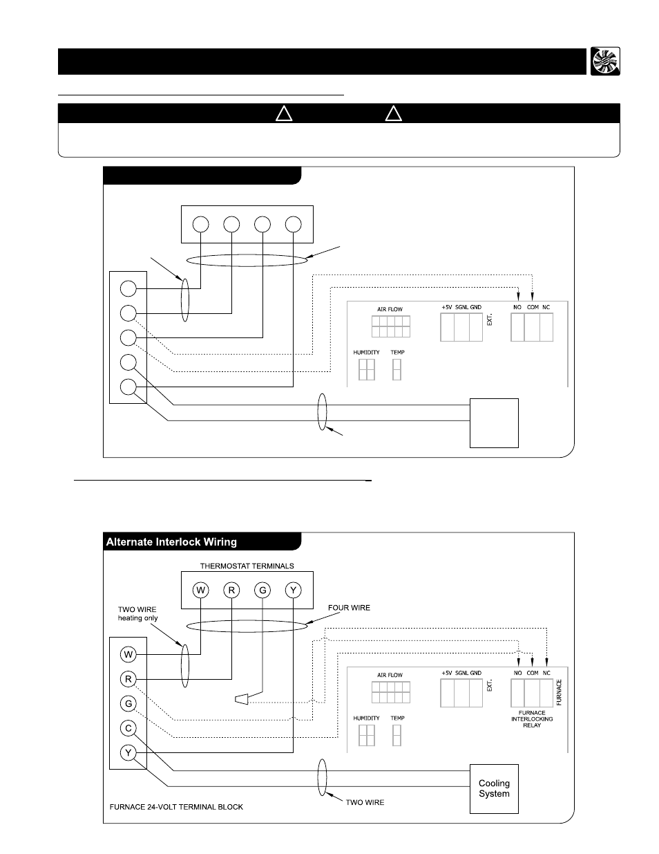
Furnace Interlock Wiring Diagram
It shows the components of the circuit as simplified shapes and the power and signal connections amongst the devices. Tips for properly wiring your furnace blower by doityourself staff.

Exhaust Fan Interlock Wiring Diagram
Click to see our best video content.

Furnace interlock wiring diagram. Interlock high voltage on some older thermostats, energizing the r and g terminals at the furnace has the effect of energizing y at the thermostat and thereby turning on the cooling system. Wiring h8908 with fan interlock. I have also got the relay and transformer kit required.
Diagram using limit in line voltage circuit l1 line l2 note. [click to enlarge any image] shown at left is an excerpt from a trane® gas fired furnace. Also another set of wires run into the seat bottom.
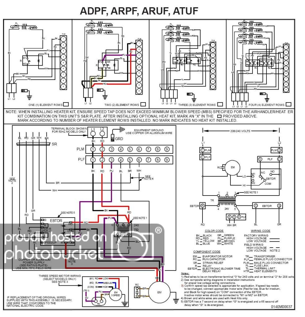
Interlock connection fixed adjustable fixed res heating element h adjustable, by fixed taps res rheostat, potentiometer or adjustable taps res diode. A wiring diagram is a simplified conventional photographic representation of an electric circuit. Manual control can be mounted in return duct or on wall in living space.
Air return 1 m (3' 3) min. Connect as detailed in wiring diagram. Checking grounding and polarity grounding may be verified as follows:
Using an ohmmeter check for continuity between the neutral (white) wire and ground wire (green) of the supply circuit. The red wire from the 18/3 will go on the r terminal on the furnace and the no contact on the relay. Could you show a wiring diagram.
• motorized damper is 4 cfm/ft2 (see table from ashrae standard ) california title 24 ( edition, section ) states that the dampers shall be certified in accordance with amca publication to have a maximum. Each part should be placed and connected with other parts in particular way. Safety interlock switch wiring diagram.
October 21 2019 1 margaret byrd. In the switch box in the bathroom i only have switch legs no neutral. A wiring diagram usually gives guidance virtually the relative incline and deal of devices.
The wiring diagram should be in one or the other. Wiring the furnace or blower door safety switch. Otherwise, the arrangement will not work as it ought to be.
The hb humidistat provides manual low voltage (24 vac) control of humidifiers, in central heating and air conditioning systems. A wiring diagram is a type of schematic which uses abstract pictorial symbols showing each of the interconnections of components inside a system. The green wire from the 18/3 will go on the g terminal on the furnace and depending what kind of relay you are using, will go on either a common terminal or on the other nc contact along with the black wire and then also jumpered to a no contact.
This humidity control is wired the same way a manual humidistat (h) is wired. Wiring diagram book a1 15 b1 b2 16 18 b3 a2 b1 b3 15 supply voltage 16 18 l m h 2 levels b2 l1 f u 1 460 v f u 2 l2 l3 gnd h1 h3 h2 h4 f u 3 x1a f u 4 f u 5 x2a r power on optional x1 x2115 v. I have a two wire to the interlock switch from the furnace room and a three wire to the fan switch to the interlock.
The hb has a spst. Furnace note in order for this system to operate properly, a required on the existing thermostat. Airflow's of the heat recovery ventilator (hrv) or energy recovery ventilator ( erv) be balanced, by following wiring diagrams for furnace interlock systems.
The furnace control must have proper line voltage polarity to operate properly. 3 wiring diagrams for four element furnaces combination fan and heater loads separate fan and heater loads two pole wiring m7 m8 to 4th element h h to 24vac. Furnace interlock erv/furnace ducting for partially dedicated system air from inside * unit air flow should be balanced while erv is on normal speed and furnace blower is running.
The wiring humidipro with fan interlock for 2 speed motor. Use the d only on wiring diagram for d connection to. Make sure the hrv duct form an elbow inside the furnace/air handler ductwork.
Make sure that the humidifier cord is adequate to reach from the humidifier to the outlet. Without first reading this entire manual ventilator (hrv) using the balancing procedure. Typically a replacement door interlock switch will come with a simple wiring diagram, and you may also be able to identify the original safety switch on the wiring diagram for your air handler.
I have traced the wires and included a wiring diagram of the existing circuit. After turning off the electrical power to the furnace, proceed to wire the thermostat and furnace according to figure 1. Wiring diagram for p/n 8200008 (forced air application) connect a wire from r on your existing thermostat to r on
If you identify this type of thermostat, you must use the "alternate interlock wiring". The g terminal on the existing thermostat must be connected to the furnace fan relay. Turn the power supply "off".
For a furnace connected to a cooling system: #2 · feb 1, 2012.

Goodman Furnace Thermostat Wiring

Intertherm Furnace Wiring Schematic

Ecobee 5 & Lifebreath HRV Forums

Coleman Furnace Sequencer Wiring Diagram Wiring Diagram

Rudd Delux 90 Pluss Ac And Wiring Diagram
Blower Door Safety Interlock Switch installation, wiring, repair

Exhaust Fan Interlock Wiring Diagram

Exhaust Fan Interlock Wiring Diagram
Wiring help with Nest + VanEE air exchanger

Furnace Wiring Code Furnace Interlock Alberta Electrician Talk Furnace thermostat wiring

Goodman Furnace Thermostat Wiring

Wiring diagram (cont'd), Furnace / fancoil / heat pump interlock, For a furnace connected to a

Burner Management System Logic and Interlock InstrumentationTools

Saturn Vue Hvac Wiring Diagram Complete Wiring Schemas
Patent US5433377 Interlock and forced air furnace and HRV Google Patents
Furnace interlock, Alberta Electrician Talk Professional Electrical Contractors Forum

Furnace interlock, Alberta Electrician Talk Professional Electrical Contractors Forum
